Software Operation and Usage
App Usage
From the app the Puck can run several different sensor modes at the same time as well as log all the data and even function as an ITC device.
Main Screen
Allows selection of the desired mode. After starting the app the Digital Dowsing logo will disappear and the Puck image will appear to indicate it is connected.
Min/Max
Shows the basic sensors of the puck and the current values of the minimum or maximum reading.
Data
Shows various sensors in graph form.
Log
Shows the Puck data as it is collected the log is saved in CSV format for use with spread sheets to track the data.
Capture
Allows the Puck to trigger the audio and image functions of the connected phone to take pictures and capture sound based on changes in the sensor array.
Settings
The speaking voice may be changed from male, female and child. The rate the device speaks at may also be adjusted.
| Screen | Name | Description |
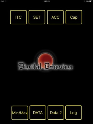 |
Main Screen – Puck 2 Disconnected | The Main Screen will appear when the application is first opened. While the Puck is not connected it will show the Digital Dowsing Logo. |
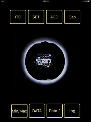 |
Main Screen – Puck 2 Connected | Turn on the puck after a few moments you should see the Puck appear on the Screen. This indicates the puck is connected and ready tossed data. “ Make sure your wireless is enabled on your device” |
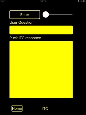 |
ITC Mode | The Slider ‘top Right ‘ should be set to the far right when learning to use this function. The farther the slider is to the right the longer responses are a loud. To start type a question in the User Question Box by touching in side the box a key Board will appear on the screen. After the question is entered hit the enter button and the puck will start sending data agin. You will see a small spinning disc in the lower right while the puck is looking for a energy response. If a response comes through you will hear the puck software speak then the spoken words will appear on the screen as well. These responses are saved in the log file. To exit press the home button. |
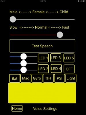 |
Settings | You can select the type of speech Male – female or child Then you can select the speed at which the voice is heard. Press the Test Speech button to hear the new settings You can control the Pucks LEDS from here as well press the Led button and the light will appear press again it will go off. Moving the Sliders will allow you to control the colors. This screen will have more functions for alarm settings in latter versions. Bat /Mag/Gyro etc. These buttons will poll the Pucks internal sensors and display The values in the text area bellow them.The Alarm Screen “ACC” is were you set the stand a lone modes It’s the first line of buttons on that screen. If you press: ION – The Puck will start up and light around the base with the light color and intensity based on Static Electricity %H – The Puck will start up and make an alarm sound when the humidity increase or decreases Bpsi – The Puck will start up and make an alarm sound when the Barometric pressure increase or decreases Move- The Puck will start up and make an alarm sound based on vibration or movement All – The Puck cycles through all offline modes repeatedly Note: Where the puck is reading items like humidity and temperate the puck will play a series of tones indicating After selecting the mode, That mode will become active the next time you power on the device. |
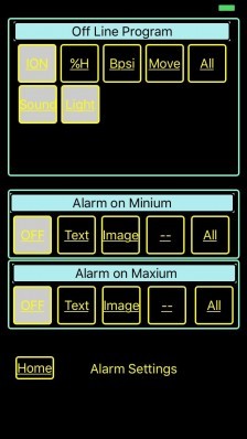 |
Alarms and Offline/Standalone Settings | When this page loads it will show you what alarm and functions are currently set in the Puck Offline are the functions the Puck will do when it is not connected to software. Also sound and light functions can be turned off from this point as well. Say you only want alerted by light or sound. By selecting the function The puck will ignore using sound or light if turned off. This will take effect after the Puck has been turned off and then back on. Next are the Trigger Alarms: They are not functional in the early release, but will go on line soon. they will let you capture a picture or sound based on data readings from the puck. Press home to exit this screen |
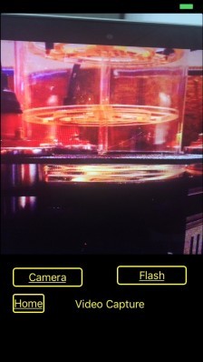 |
Video Capture | The Capture screen Show the view from the device camera,
Capture of images can be turned on in the Alarm’ACC’ screen You may select text alarms Written to the log file Image Alarms Pictures will be take and saved to the picture folder Both Alarms Save images and text. iOS users can select camera and flash option here ** Camera settings are not yet available on the android version |
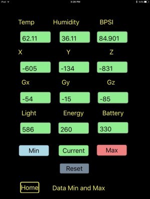 |
Min / Max | This screen show the current sensor data from the Puck. Pressing Min Max of current will change the text colors and display the Min Max or current value for that sensor. Reset will clear the Minimum and Maximum values. We recommend that you allow the puck to run for a few minutes then clear. Press Home to exit. |
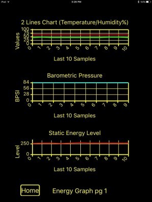 |
Data 1 | Shows the last ten sample from the sensors as a graphic chart. Press Home to exit. |
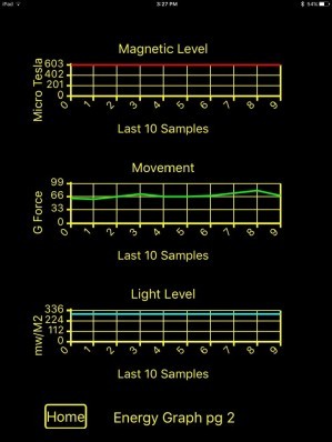 |
Data 2 | Shows the last ten sample from the sensors as a graphic chart. Press Home to exit |
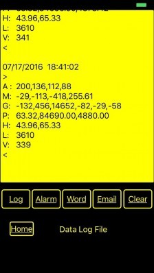 |
Log | Swipe up or down to see the log file it records ITC session data and all sensor data. The Log can be cleared “Deleted” by pressing the Clear button. A = Static 1,2,3,4 Internal Antenna Logs are now divided for faster viewing Log is the master log with all entries Alarm is the Alarm state logs only Word is the Log of ITC sessions |
