Scanning Radio AKA Ghost Box – Installment 2
Project Overview
This is part 2 of a DIY Scanning Radio Ghost Box series using an Arduino Uno which was launched on Twitter as part of the Bread Boards & Bill series.
Prior to continuing forward the steps in DIY Ghost Box Installment 1 need to have been completed.
In this installment we are adding more features and improving the functions for the software and hardware.
Future installments will build upon the steps in these instructions.
Reference
The following is the pdf version of these instructions which includes additional information and tips beyond the instructions in this web guide.
Materials Needed
This section will require a microphone to add the Speak When Spoken To option.
- Breadboard – Breadboards come in a wide variety. For this project, most any will work. Consider buying a multi-pack or a bundle that has jumper wires included. Available from Amazon and many other retailers. As we do more projects this year, a breadboard will make the builds easier.
- Short bare wire 2-3 inches long – you can remove the coating of one of your existing jumper wires
- Microphone which allows the Speak When Spoken To option
Building
Hardware Setup
It’s time to add a breadboard to the project. A breadboard will allow for more devices and a cleaner method of connecting items to the Arduino Uno.
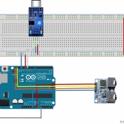
The microphone connection has three leads:
- VCC, connected to Arduino pin 12
- Ground, connected to Arduino Uno GND
- Out, connected to Arduino Uno pin 11.
Later on in the example code, you will also see an output called BreadBoard. This output is used to power the breadboard when the program is running aids in keeping parts safe from mistakes while setting things up.
One last item needed is a short bare wire 2-3 inches long; this wire will act as an antenna responding to EMF and Static electricity.

Software Setup
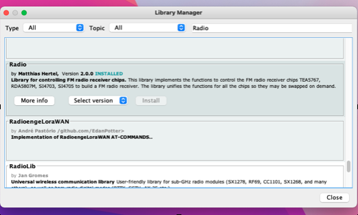
- From the Tools menu, open the Library Manager.
- Next, in the Library Manager search bar, enter radio.
- Select the Radio Library and Install.
- Close the Library Manager when done.

Source Code
- Use the link below to download the new Arduino program file or cut and past from the code below.
- Save it to your computer and open in the Arduino IDE editor (the file is in a zip format.).
Part 2 Arduino source code zip file
//******************************************************************************************
// Ghost Box program scans up then down flashes led on UNO indicates sweeping
// Microphone add and new library Mutes while not scanning
//*********************************************************************************************
/// \file  TestTEA5767.ino
/// \brief An Arduino sketch to operate a TEA5767 chip based radio using the Radio library.
///
/// \author Matthias Hertel, http://www.mathertel.de
/// \copyright Copyright (c) 2014 by Matthias Hertel.\n
/// This work is licensed under a BSD style license.\n
//
//  Sketch modified for the Simple ghost box project 1/20/2022
//
//*********************************************************************************************************
//  Includes
//*********************************************************************************************************
#include <radio.h>                                     // Library
#include <Wire.h>                                      // SLC SDA communications for radio module
#include <TEA5767.h>                                   // Tells Radio library how to interface the radio module
TEA5767 radio ;                                        // Define radio model
//*********************************************************************************************************
// Global Variables
//*********************************************************************************************************
int LED1 =13;                                         // create a name for led1 on the arduino
int hold =20;                                         // hold is the delay time
int inc = 20;                                         // How far to move when tunning
int start_FM = 9230;//8790                            // US FM Band start **87.7 excluded
int stop_FM = 9990;//10790                            // US FM band stop
int breadboard = 12;                                  // power pin to breadboard
int mic = 11;                                         // microphone signal
int AntIn = 0;                                        // antena energy value 1 count = 1.1 / 1024 = .0010 volts
//*********************************************************************************************************
// Program Setup
//*********************************************************************************************************
void setup()
{
  pinMode(LED1, OUTPUT);                               // led on board led
  pinMode(breadboard  , OUTPUT);                       // breadboard power
  Wire.begin();                                        // start IC2 communications
  digitalWrite(breadboard, HIGH);                      // power ON breadboard
  radio.init();                                        // Start radio
  radio.setMute(1);                                    // Mute ON radio sound off
  delay(100);                                          // allow breadboard to power ON
}
//*********************************************************************************************************
// Main program
//*********************************************************************************************************
void loop()
{
  delay(10);                                          // allow analog time to settle
  AntIn = analogRead(A0);                             // read energy on antenna
  radio.setMute(1);                                   // radio mute ON
  int a = digitalRead(mic);                           // read mic to a

  // to talk or not to talk
  if ((AntIn > 400) or (a == 0))                      // if Antin is greater  than 340 or a = 1 mic on then scan
  {
    while (a == 0)                                    // while mic = 1 wait here
    {
      delay(5);                                       // delay 5 ms
      a =  digitalRead(mic);                          // read mic to a
    }
   delay(500);                                        // wait 1.5 seconds before responding
   radio.setMute(0);                                  // un-mute the radio and allow it to scan

  // for loop and scan from start-FM to stop-FM stepping by inc value in MHz
   for ( int r = start_FM; r <= stop_FM;r = r+ inc)
   {
    digitalWrite(LED1, HIGH);                         // led ON
    radio.setFrequency(r);                            // Set radio to new frequency
    delay(hold/2);                                    // wait here for 1/2 of hold
    digitalWrite(LED1, LOW);                          // led OFF
    delay(hold/2);                                    // wait here for 1/2 of hold
   }

//     for loop and scan from stop-FM to start-FM stepping by inc value in MHz ** -/+ inc to prevent repeat scan
    for ( int r = stop_FM-inc;r >= start_FM+inc;r = r- inc)
   {
    digitalWrite(LED1, HIGH);                         // led ON
    radio.setFrequency(r);                            // Set radio to new frequency
    delay(hold/2);                                    // wait here for 1/2 of hold
    digitalWrite(LED1, LOW);                          // led OFF
    delay(hold/2);                                    // wait here for 1/2 of hold
   }
  }
}
//*********************************************************************************************************
// End of program
//*********************************************************************************************************
Testing
- Download or paste the new code into the Arduino IDE editor.
- Click the right arrow ‘Left top of the IDE screen.’
- The IDE editor will compile the new sketch and upload it to your Arduino Ghost Box project.
- See the attached PDF in the reference section for additional tips on changing this code to alter functions.
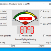
Example Result
Looking Ahead To Installment 3
In the next installment, we will discuss adding a display and doing more with the antenna and power.
The Ghost box can function without being connected to a computer.


 digital dowsing 2022